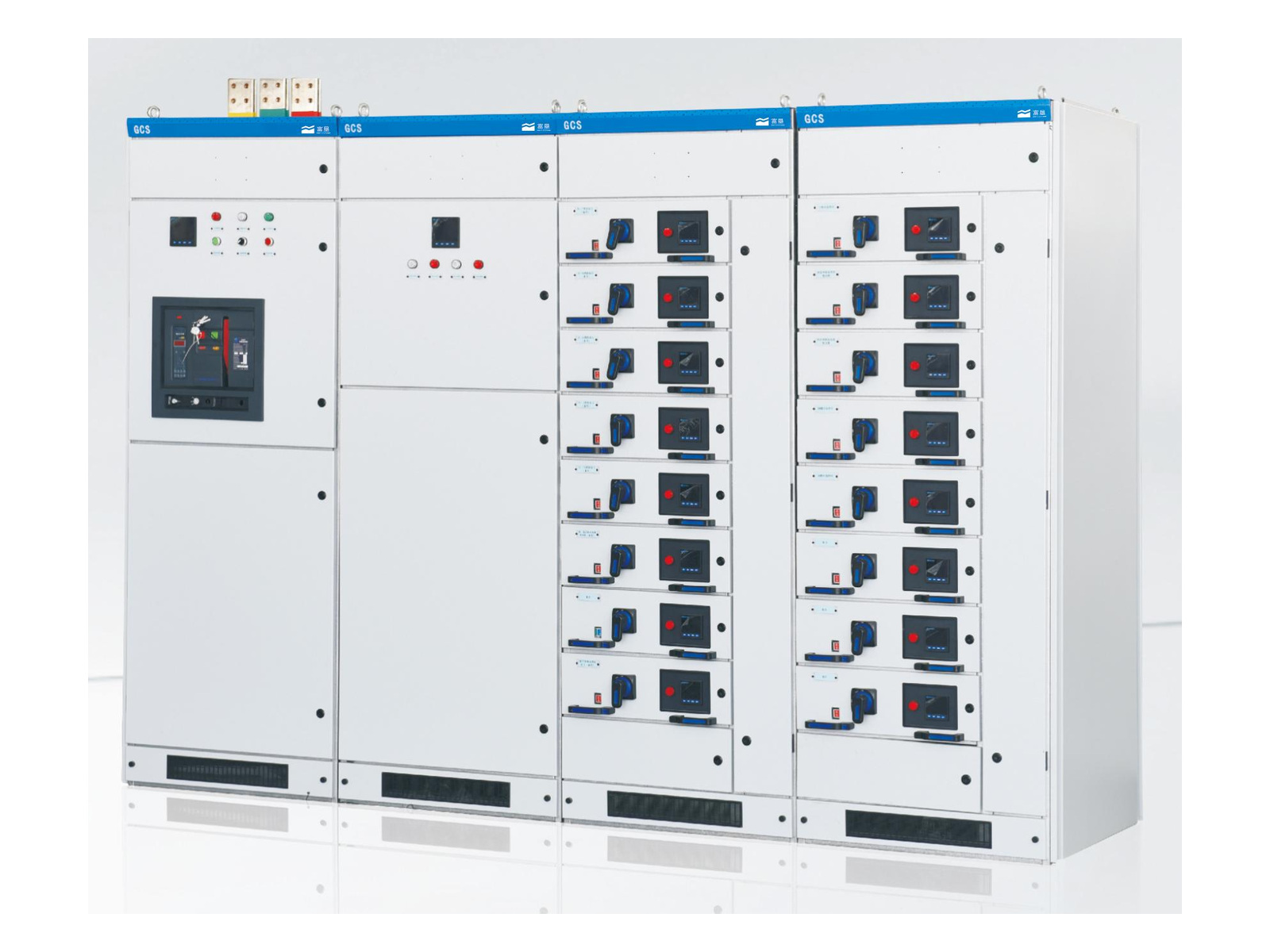
Low-Voltage Switchgear
GCS Drawer Switchgear
Withdrawable low-voltage switchgear for power distribution, centralized motor control and reactive power compensation.
View productLow-voltage switchgear supplies and controls the outgoing circuits of a low-voltage distribution system. GCS drawer construction groups devices into withdrawable functional units for distribution and centralized motor control. Reactive power compensation is a separate configuration to be specified against the project load and target.
1 product · Showing 1–1
Low-Voltage Switchgear
Withdrawable low-voltage switchgear for power distribution, centralized motor control and reactive power compensation.
View product ↗The essentials
Low-voltage switchgear groups the devices needed to distribute power and operate connected loads within a low-voltage system. The available GCS range uses withdrawable drawer units for functional circuits, supported by horizontal and vertical busbar arrangements. Distribution, centralized motor control and reactive power compensation are different configurations with their own device and control requirements.
How it works
The main incoming circuit breaker connects the low-voltage supply to the busbars. The busbar system then carries power to the outgoing feeder units. The selected incoming arrangement and feeder circuit design determine how electrical power reaches the distribution, motor-control or compensation circuits included in the switchgear.
Each outgoing feeder uses the protective device specified for its load, such as a moulded-case or miniature circuit breaker. The device disconnects the circuit when its overload or short-circuit operating criteria are met. Device selection and coordination determine how the feeder protection interacts with the main incoming protection.
Where motor-control circuits are included, contactors connect and disconnect the motor supply in response to the control commands. Thermal relays provide the specified motor overload protection. Together, the switching and protective components perform the start, stop and overload functions required by the selected motor-control arrangement.
Where a reactive-power compensation unit is specified, automatic switching connects or disconnects capacitor banks to adjust compensation as the load changes. This can improve power factor and reduce the current associated with reactive demand. The achievable power factor depends on the load profile and the selected compensation arrangement.
Project enquiries
Share the electrical ratings, circuit functions and installation conditions for a configuration review.
Why this category
Before you specify
The published range lists 380 (400) / 660 V AC and 50 / 60 Hz options. Voltage, frequency, busbar duty and functional-circuit ratings must be confirmed together for the selected configuration.
Provide the motor list, rated currents, starting methods, operating sequence, control voltages and interface requirements. These details determine the functional-unit arrangement and the devices required in each circuit.
No. The horizontal busbar, vertical busbar and individual functional circuits have different duties and ratings. The listed maximum horizontal busbar value is configuration dependent and does not establish the rating of each outgoing circuit.
A target must be assessed against the actual load profile and electrical system. Specify the compensation requirement and relevant load characteristics; a fixed power-factor result is not guaranteed by the GCS model designation.
Check the existing drawings, dimensions, busbars, connection interfaces and device ratings before assuming compatibility. Withdrawable construction does not establish that a new drawer or cabinet section will fit an existing assembly.
Project enquiries
Share your specifications, drawings and installation conditions. We can review the appropriate product and configuration.
Explore practical information for your next equipment enquiry.